TryEngineering Hands-on Activity
Internet of Things
The main aim of this project is to help people in their daily lives as many people due to workload, stress, or due to any other issues usually get late and be forgetful regarding their home keys. This project can be very helpful for them as it will allow a secure and key-less entry to their homes. As Security is a major concern in our day-to-day life, and digital locks have become an important part of these security systems. There are many types of security systems available to secure our place and this project can provide security at the same time for places and safety deposit boxes.
This project is based on a custom-made ‘Arduino’ through which the algorithm for knock pattern detection is composed as it is also programmable. So when you press the tactile/push button and insert a new knock pattern, it will open only on the new one, as the speaker is going to catch the knock and will open the door by recognizing the knock pattern. We have added two LEDs which are used for enlisting or registering of new knock patterns. The ‘Arduino’ is going to coordinate with the knock designs along with the knocking algorithm and will open the door if the knock pattern matches the saved one.
Topic Areas
- Internet of Things (IoT)
Age Range of Students
- 11-13 years
- 14-18 years
The hands-on activity objectives include:
- To highlight the challenges of losing keys in one’s busy everyday life and that may lead to stress, anxiety, and inconvenience.
- To show how our proposed project can facilitate the user by providing effective way of managing home security via smart door.
- To provide understanding of how smart devices can work in the field of internet of things (IoT).
At the end of the demonstration, the students will be able to identify the threats and vulnerabilities associated with the house’s main entrance. A brief overview of the IoT provided during the demonstration will also help them gain more insight into the growing and interesting field of IoT. Nevertheless, detailed description and demonstration of the components will help them identify the usability of various components that have been used in this project. Moreover, this hands-on activity will give them an opportunity to identify challenges in everyday life and be creative to help resolve those.
Following components have been used in this project:
- Arduino NANO
- Transistor
- Solenoid lock (12V)
- Speaker
- LEDs (green and red)
- Resistors (220Ω, 10KΩ, 1MΩ)
- Tactile/push button
- Jumper wires
- Diode
- 12V Adaptor
- Breadboard
- PCB board
- First take the bread board and start assembling the components first we attached the arduino nano in the starting holes of bread board in series.

Figure 1: Arduino Nano board is attached on the breadboard - After that, leaving four holes of bread board, we attach the tactile/push button in the same vertical direction to the Arduino Nano.

Figure 2: Push button along with the Arduino nano is attached in the breadboard - Then we place the LEDs soldered with the 220Ω resister connecting with the arduino’s digital pins first one with D4 and the second one with D5.

Figure 3: Connecting LEDs with Arduino via 220Ω resistors. - With that a terminal of jumper wire is connected to ground leaving one hole of the bread board and the other terminal with the left back leg of the tactile/push button.
- With the push button’s right side’s back leg, a 10kΩ resistor is connected parallel to it leaving two holes of the bread board.
- Then connect a jumper wire on the forward left leg of the tactile/push button with the arduino’s digital pin 5V.

Figure 4: The components are connected to Arduino nano using jumper wires - Now connect a terminal of jumper wire in series with 10kΩ resister to the ground of arduino on the other side.
- Now connect the speaker in series with 10kΩ resister and also in the same direction with arduino and also connect a 1MΩ resistor in parallel with the speaker.
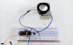
Figure 5: Speaker is attached with the circuit - Connecting a terminal of jumper wire parallel with the 1MΩ and the other terminal with arduino’s digital pin A0.
- Then connecting the relay with jumper wires and connecting right jumper wire with D3 and connecting the middle one with the digital pin 5V and the left one with the ground pin of arduino.
- Then we connected a diode with solenoid lock by soldering and by that connect it with the adapter connector with negative wire of adapter and solenoid lock with that connector.
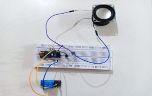
Figure 6: Connecting relay with the circuit - Now connect the positive terminal wire of the adapter with relay and also the positive side of solenoid lock.

Figure 7: Connecting Diodes with the relay - Afterwards we turned on the main connection and tested it with the bread board and as we saw that it worked on the bread board connections then it also must work on the PCB board, according to that we now will shift all the connections in the same way on the PCB board in accordance with the diagram which we have made.
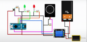
Figure 8: Complete circuit diagram of the
digital door locking project
Figure 9: PCB circuit diagram of the project 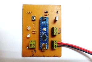
Figure 10: Components placed on the PCB 
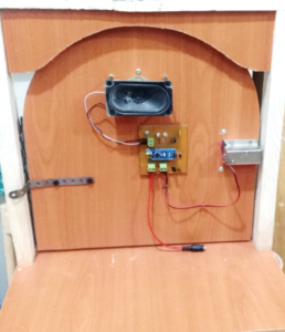
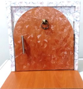
Figure 11: A complete product of digital door locking system
Thanks to the IEEE Communications Society (ComSoc) and it’s members who created this hands-on activity:
- Tooba Aftab Arisar
Lesson Plan Translation