Sponsored Lesson by KEYSIGHT Technologies

This lesson plan explores basic circuits using unique materials and going deeper with simulations. Students apply what they learn in a design challenge to make a light up name badge.
Students explore series and parallel circuits in a simulated environment and then replicate their best design using the paper circuit materials.
Students will be able to understand:
- Basic components of a simple circuit
- Electronic component symbols
- Series and parallel circuits
Age Levels: 10 – 17
Lesson Plan Presentation
Materials & Preparation
Required Materials
Copper Tape – 1ft – 2ft per student
LEDs (10mm is best) – 3-4 per student (extra if a leg breaks)
Coin Cell Batteries (3V- CR2023 works) – 1-2 per student (second for testing more LEDs)
Index Card – Up to 3-5 per student (extra are for testing, mistakes)
Table of Possibilities (pipe cleaners, googly eyes, colored paper, feathers, binder clips, paper clips, Tape/Glue, Scissors, Markers, etc). Items are for for decorating and attaching name badge
Computers
PHet Simulations (Circuit Construction Kit: DC)Materials & Preparation
Required Materials
- Copper Tape – 1ft – 2ft per student
- LEDs (10mm is best) – 3-4 per student (extra if a leg breaks)
- Coin Cell Batteries (3V- CR2023 works) – 1-2 per student (second for testing more LEDs)
- Index Card – Up to 3-5 per student (extra are for testing, mistakes)
- Table of Possibilities (pipe cleaners, googly eyes, colored paper, feathers, binder clips, paper clips, Tape/Glue, Scissors, Markers, etc). Items are for for decorating and attaching name badge
- Computers
- PHet Simulations (Circuit Construction Kit: DC)
Engineering Design Challenge
Paper Circuit
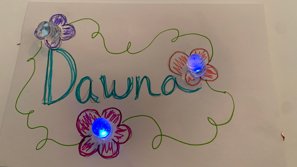
You have been given the challenge of designing, constructing, and wearing a light up name badge that shows your name.
Criteria & Constraints
- Three LEDs must be part of your name badge & all must light up
- Use only one coin cell battery
- You must be able to wear your name badge
- Use only the material available
- Use a simulation tool to iterate and get the best solution
Activity Instructions & Procedures
Phase 1: Whole Group Demo of Phet Basic Circuit
Phase 2: Phet Simulation: how to get 3 LEDs to light with one battery?
Phase 3: Design & Construct your Light up Name Badge
Introduce the Lesson: Read the design challenge and constraints.
- Hold up sample light up name badges materials they will use
- Put on your light up name badge
- Explain that before we can make this we need to do some playing first!
Phase 1: Whole Group Demo of Phet Basic Circuit
- Open PhET Simulations to Circuit Construction Kit: DC. Click the play button on the image and choose Intro. There is also an AC simulation (see vocabulary list). Either will work for this challenge.

Note: Computer-based simulations help students understand complex concepts by having them manipulate on-screen components. Simulations allow students to see how systems or processes work through immediate cause & effect response. They “play” and iterate until they complete the task. - Show them the light, battery and wires.
- Ask for students to sketch what they think the circuit should look like.
- Invite one student to come up and “make” their circuit in PhET
Point out possible pitfalls
- Students often think that they can put the both wires on the bottom of the bulb when placing it into a circuit but they quickly realize that shorts the circuit. One wire must connect
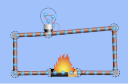 on the side of the bulb and the other to the bottom of the bulb. This can visibly be seen by the two bulbs not lighting up in the top image and then when correctly connected the bulbs light up.
Phase 2: Phet Simulation: How to get 3 LEDs to light with one battery?
- Now give the students the challenge to individually or in teams of two to work to get three LEDs to light. Have them test putting the LEDs in series and parallel.

Series

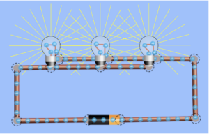
Parallel

Note that in series you need a second battery to get the three LEDs to light up brightly. However, in parallel you only need one battery.
Phase 3: Design & Construct your Light up Name Badge
Make your Name Badge
- Begin by having students brainstorm ideas for their name badge design. Have them take a look at the materials available on the Table of Possibilities.
Where do they want to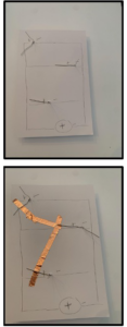 place their lights? Will the lights be in a specific spot in the design (i.e. dot of an” i” or in the middle of an “o”, or in the center of a star or the sun)
 - Show the samples again. Specifically pointing out those that have the name on the front and the circuit on the back and those that show the circuit, etc.
- Share the required materials and introduce them to your table of possibilities
- Explain that there can be multiple solutions to the same problem. For this challenge. there’s no one “right” solution. Designs that work and meet the criteria of lighting up an LED will look very different. There will be multiple solutions.
- Have students begin by replicating their best circuit from Phet on your index card. Using pencil, sketch it out. Where the LED’s go, battery and wire, your name, etc. Have them consider: Based on what you learned with the simulation, what would be the best choice for one battery and three LEDs (series or parallel)? Consider starting with that choice. The simulations indicate that parallel would be the best option for one battery and 3 LEDs. It showed that two batteries would be required to make the LEDs light-up bright in series.
- Next they assemble the circuit for their name badge. Poke the LEDs through and lay down just the long leg of all your LEDs (positive) and tape those down with the copper tape (wire). Next tape down all the short legs of LEDS and then press all the connections down well and close the circuit by pressing hard on the battery (acting as a switch with the negative line going under the battery and the positive line going to the top of the battery).

- Students decorate their badge and design a way to wear it so others can see it (see sample – using pipe cleaners to make it into a necklace).


Share the Tips and Tricks:
- Both the LED and coin cell battery have a Positive and Negative end. Notice the positive leg of the LED must connect with the positive side of the coin cell battery and same for the negative side.
- Test your battery and LED to ensure your components work prior to assembly. Put the long leg of the LED to the top (+) side of the coin cell battery and the short leg of the LED to the bottoms (-) side of the coin cell battery. How many LEDs can the coin cell battery power in parallel? (add more LEDs to your test).

- Shorting a circuit: Be mindful to not have your copper tape overlap where it shouldn’t- resulting in the breaking of the current flow. (i.e. putting copper tape across the circuit, be careful with the coin cell battery as the side of it is also positive.)
- The copper tape will be your WIRE. It has adhesive on the back; just peel off the paper.
- To get good connectivity you need pressure…make sure to press down on the LED legs and consider adding cooper tape both below and on top of the legs
- Your coin cell battery acts like a switch. When you press on it, it closes the circuit.
- To keep your light on, tape it down.
- LED legs can break off easily. Be mindful to not bend too sharply.
LED colors can be tricky. To keep it simple use only one color for this project. Each color LED requires a different voltage to light up (for example: Red:1.8V, Yellow: 2.1V, Green: 2.2V, Blue: 3.2V and White: 3.2V). So depending on the combination, it may not work for you to use 3 different color LEDs in this project. To learn more check out this video by Q26: All About LEDs Part 2: Mixing Different Colors
Time Modification
The lesson can be done in as little as 1 class period for older students. However, to help students from feeling rushed and to ensure student success (especially for younger students), split the lesson into two periods giving students more time to brainstorm, test ideas and finalize their design. Conduct the testing and debrief in the next class period.
Engineering Design Process
Background Concepts
What is a Simple Circuit?
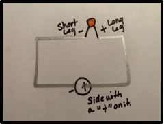 A simple circuit consists of three components: a source of power or electricity (coin cell battery), a path or conductor (wire – copper tape) on which electricity flows (current) and an electrical resistor (LED). This image shows a simple circuit containing one coin cell battery, two pieces of copper tape (wire) and an LED. The flow of electricity (current) is from the positive (+) side of the battery through the LED (lighting it up), and back to the negative (-) side. To make the LED light we must connect the positive leg of the LED to the positive side of the coin cell battery and the negative (short leg) with the bottom of the coin cell battery. (See PPT for a single LED name badge)
Current: Current flows from a high voltage (+) to a lower voltage (-) in a circuit. Some amount of current will flow through every path it can take to get to the point of lowest voltage (usually called ground).

Series Circuit: Components are connected end-to-end in a line forming a single path for the current to flow. Each component in a series circuit shares one node with its nearest neighbor. LEDs are linked in series with the negative leg of the LED connected to the positive leg of the next LED and so on.
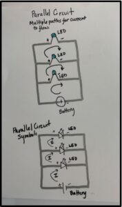 Parallel Circuit: Components are connected across each other’s legs- positive to positive and negative to negative. There are many paths for current flow, but only one voltage (battery) across all components. Positive legs of LEDs connect to the positive end of the battery and negative legs of LEDs connect to the negative end of the battery.
Vocabulary
- Battery: Powers the circuit. When the battery is in a closed circuit it will convert chemical energy to electrical energy (electricity) to power the circuit (i.e make current flow and light the LEDs)
- Current: Flow of electrical energy (electricity) through a circuit
- LED: Type of semiconductor called “Light Emitting Diode” (LED). It will light-up when current is flowing through it. Positive (long) leg is the “anode” and the negative (short) leg is the “cathode”
- Wire: Conducts electricity and is used to connect components in a circuit
- AC: An alternating current (AC) is an electrical current that regularly reverses direction and changes its value constantly with time
- DC: A direct current (DC) is an electric current that flows through in one direction
- Closed Circuit: When the switch in the circuit is closed and current can flow
- Open Circuit: When the switch in the circuit is open and current can not flow
- Switch: A switch in a circuit is used to open or close the circuit. Closing off or opening the flow of current
- Short Circuit: When wires that are not supposed to come in contact with each other touch (overlap in someway)
- Condutor: Material that allows electricity to flow through it
- Insulator: Material that does not allow electricity to flow through it
- Resistance: Insulation is measured in resistance. The more insulating a material, the more resistance it has
- Parallel Circuit: Allows multiple paths for electricity (current) to flow through
- Series Circuit: Allows one path for electricity (current) to flow through
Dig Deeper
Extension Activities
- Clean Energy: Discuss the use of LEDs in the world.
SDG 7: Affordable and Clean Energy
“About 50% of global residential lighting sales use LED technology. To align with the Net Zero Emissions by 2050 Scenario, progress in this area must be sustained to 2030 to ensure that all countries sell predominantly LED technology and with increasing efficiency.” Source: Lighting IEA- Why are LEDs part of the clean energy strategy?
- Do you use LEDs in your home, your school, etc?
- Develop a plan to convert to LED light where it is not currently being used.
Dive deeper Into Conductors and Insulators on the PHet Simulations (Circuit Construction Kit: DC). Explore the different materials (insulators and conductors) in the simulation.
Curriculum Alignment
Alignment to Curriculum Frameworks
The “Notes” column explains how the lesson connects to STEM topics and a “X” indicates at what level (beginner, intermediate, advanced). Please note a large “X” indicates a strong connection and a small “x” indicates a weaker connection or opportunity to make a connection.
Science Topics Notes Beginner Intermediate Advanced Materials & Properties Use of unique materials: copper tape for wire and a coin cell battery (these may be new to students). This paper circuit is the same as building a circuit on a breadboard. Creative use of material for how to wear the name badge. x Energy Could discuss energy conversion within the battery (chemical to electrical) x Electricity/Magnetism Basic circuits (series and parallel) X Physics (light, sounds, heat) Gaining understanding of how LEDs work X Technology Topic Notes Beginner Intermediate Advanced Systems Open and closed circuit X Design & Innovation (EDP) Engineering Design Process (EDP) X Sustainable Development Goals (SDGs) Alignment – Lessons are aligned based on if the lesson could be used to address any of the SDGs (https://sdgs.un.org/goals).
SDG 7: Affordable and Clean Energy
Ensure access to affordable, reliable, sustainable and modern energy for all.x Discuss use of LEDs around the world. Related Engineering Fields and Degrees
Student Worksheet
Instructions
DESIGN CHALLENGE: Paper Circuit
The Challenge: You have been given the challenge of designing, constructing, and wearing a light up name badge that shows your name.
Criteria & Constraints
- Three LEDs must be part of your name badge & all must light up
- Use only one coin cell battery
- You must be able to wear your name badge
- Use only the material available
- Use a simulation tool to iterate and get the best solution
STEP 1: Simulation – How to get 3 LEDs to light with one battery?
- Play with putting the LEDs in series and parallel.
- What were some key findings you discovered?
STEP 2: Make Your Name Badge
- Brainstorm your name badge design. Where will you put the LEDs?
- Based on your findings from the PhET circuit simulation. Determine how you will be putting the LEDs into the circuit- series or parallel? Using a pencil, sketch your circuit.
- Next they assemble the circuit for your name badge. Poke the LEDs through and lay down the copper tape one LED at a time. See Tips and Tricks list below
- Decorate your badge and design a way to wear it so others can see it.
Tips and Tricks:
- Both the LED and coin cell battery have a Positive and Negative end. Notice the positive leg of the LED must connect with the positive side of the coin cell battery and same for the negative side.
- Test your battery and LED to ensure your components work prior to assembly. Put the long leg of the LED to the top (+) side of the coin cell battery and the short leg of the LED to the bottoms (-) side of the coin cell battery. How many LEDs can the coin cell battery power in parallel? (add more LEDs to your test).
- The copper tape will be your WIRE. It can just be ripped (you do not need to cut with scissors). It has adhesive on the back; just peel off the paper.
- To get good connectivity you need pressure…make sure to press down on the LED legs and consider adding cooper tape both below and on top of the legs
- Your coin cell battery acts like a switch. When you press on it, it closes the circuit.
- To keep your light on, tape it down.
- LED legs can break off easily. Be mindful to not bend too sharply.
LED colors can be tricky. To keep it simple use only one color for this project. Each color LED requires a different voltage to light up (for example: Red:1.8V, Yellow: 2.1V, Green: 2.2V, Blue: 3.2V and White: 3.2V). So depending on the combination, it may not work for you to use 3 different color LEDs in this project. To learn more check out this video by Q26: All About LEDs Part 2: Mixing Different Colors
Translations




 Power and Nuclear Engineering