Using Ohm's Law to Build a Voltage Divider
This lesson focuses on the voltage divider, a basic circuit of electrical engineering. Using breadboards, student teams apply Ohm’s Law to construct voltage divider circuits. Students learn how to read resistor codes and calculate resistor values.
- Understand and demonstrate the engineering design process
- Use Ohm’s Law as a tool for engineering design.
- Use a digital multimeter to collect data.
- Analyze the electrical requirements of light emitting diodes (LED’s)
Age Levels: 8-18
Prerequisites (Recommended)
Students should have a basic working knowledge of these related TryEngineering lessons
- Get Connected With Ohm’s Law
- Series and Parallel Circuits
Build Materials (For each team)
Required Materials (all materials can be reused)
- Multimeter
- Breadboard with Wire Set
- Calculator
- LED – Super Red, Clear Lens
- 9V Alkaline Battery
- 9V Battery Holder with Wire Leads
- Resistor: 100 ohm, Carbon Film, 1/2W, 5%
- Resistor: 150 ohm, Carbon Film, 1/2W, 5%
- Resistor: 220 ohm, Carbon Film, 1/2W, 5%
- Resistor: 330 ohm, Carbon Film, 1/2W, 5%
- Resistor: 470 ohm, Carbon Film, 1/2W, 5%
- Resistor: 560 ohm, Carbon Film, 1/2W, 5%
- Resistor: 680 ohm, Carbon Film, 1/2W, 5%
- Resistor: 820 ohm, Carbon Film, 1/2W, 5%
- Resistor: 910 ohm, Carbon Film, 1/2W, 5%
- Resistor: 1000 ohm, Carbon Film, 1/2W, 5%
Materials
- Use build materials
Process
Students test their circuits by lighting up the LED bulb. Students must predict and then measure the output voltage values of their circuits using a multimeter
Design Challenge
You are part of a team of engineers given the challenge of understanding how Ohm’s Law works and applying it. You’ll learn how to read resistor codes, what a breadboard is and how to calculate resistor values. Then, your team will use a breadboard to build a voltage divider circuit that can illuminate a light emitting diode (LED bulb). You must predict and measure with a multimeter the output voltage values of your circuit.
Criteria
- Use a breadboard to build a voltage divider circuit
- Use a multimeter to measure the output voltage values
Constraints
- Use only the materials provided.
- Break class into teams of 2.
- Hand out the Using Ohm’s Law to Build a Voltage Divider worksheet, as well as some sheets of paper for sketching designs.
- Discuss the topics in the Background Concepts Section and Review the Teacher Guide Section. Consider asking students if they know how a circuit works. What happens when you flip a light switch on or off?
- Review the Engineering Design Process, Design Challenge, Criteria, Constraints and Materials.
- To prepare for the activity, review the Teacher Appendix 1, 2, and 3 and the Voltage Divider Information Sheet.
- Provide each team with their material kits.
- Instruct students to complete Step 1 – Resistor Color Codes. Students review the handout on Resistor Color Codes and then determine the color codes for the resistors in their material kit. After finding each resistor in the kit, students can measure and record the resistance and determine whether the value is within the tolerance.
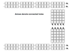
- Instruct students to complete Step 2 – Understanding Breadboards. Breadboards normally have rows of holes along each edge that are connected together. Then, running perpendicular to the edge holes, there are shorter rows with holes connected together. Oftentimes, the breadboards are split into two halves so that an integrated circuit can be placed in the middle of the board. For these boards, there will be a set of holes on each side of the split that are connected to each other, but are not connected across the split.Invite students to explore the breadboards found in their kits. In the spaces provided on their worksheets, encourage students to draw diagrams of some of the connections on the breadboards and how the breadboards may be used to build a voltage divider circuit.
Invite students to explore the breadboards found in their kits. In the spaces provided on their worksheets, encourage students to draw diagrams of some of the connections on the breadboards and how the breadboards may be used to build a voltage divider circuit. - Instruct students to complete Step 3 – Building a Voltage Divider. Using the diagram and the resistors in the lesson kit, invite students to build a voltage divider using the 9V battery, R1=820ohm, and R2=470ohm. Students can then predict and measure output voltages for their voltage dividers and record the information on their worksheets.
- Instruct students to complete Step 4 – Building a Voltage Divider for a Desired Output. Using the voltage divider circuit, challenge students to select R1 and R2 from the lesson kit to produce the output voltages listed on their worksheet.
- Instruct students to complete Step 5 – Building a Light Emitting Diode Circuit. A circuit to illuminate a Light Emitting Diode (LED) is very similar to a Voltage Divider circuit. An LED circuit replaces R1 with the LED. For an LED in this configuration, V1 will be a constant voltage, regardless of the total current. Therefore, for these circuits, V2 is also known. LED’s require a certain amount of current for optimal operation. This is called the bias current. Therefore, if V2 and bias current are known, students can calculate a value for R2.Instruct students to complete the exercises on their worksheets.
Instruct students to complete the exercises on their worksheets. - For more content on the topic, see the “Digging Deeper” section.
Extension Ideas
- Create an Excel spreadsheet that predicts all possible output voltages given a selection of resistors and batteries.
- Remove R2 from the circuit. Replace R1 with the largest available value. Connect the multimeter to measure V2, using the multimeter’s internal resistance instead of R2. Use the voltage measured to calculate the internal resistance of the multimeter.
Time Modification
The lesson can be done in as little as 1 class period for older students. However, to help students from feeling rushed and to ensure student success (especially for younger students), split the lesson into two periods giving students more time to brainstorm, test ideas and finalize their design. Conduct the testing and debrief in the next class period.
- Circuit: A complete path around which electricity can flow
- Constraints: Limitations with material, time, size of team, etc.
- Criteria: Conditions that the design must satisfy like its overall size, etc.
- Engineers: Inventors and problem-solvers of the world. Twenty-five major specialties are recognized in engineering (see infographic).
- Engineering Design Process: Process engineers use to solve problems.
- Engineering Habits of Mind (EHM): Six unique ways that engineers think.
- Iteration: Test & redesign is one iteration. Repeat (multiple iterations).
- LED: Light Emitting Diode. A semiconductor device that produces light from electricity.
- Multimeter: Electronic measuring tool that is a combination of several tools in one unit.
- Ohm’s Law: The way current flows through a resistance when a different electric potential (voltage) is applied at each end of the resistance.
- Prototype: A working model of the solution to be tested.
- Resistor: Part of an electrical circuit that resists, or limits, the power of an electrical current in a circuit.
- Voltage: Name for the electric force that causes electrons to flow. It’s the measure of potential difference between two points in the circuit.
- Voltage Divider: An electrical circuit which creates an output voltage which is proportional to an input voltage.
Internet Connections
- IEEE Global History Network
- National Council of Teachers of Mathematics Principles and Standards for School Mathematics
Recommended Reading
- Ohm’s Law, Electrical Math and Voltage Drop Calculations by Tom Henry. (ISBN: 978-0945495260)
- Teach Yourself Electricity and Electronics, Fourth Edition (Paperback) by Stan Gibilisco. (ISBN: 978-0071459334)
- Electrical Engineering 101: Everything You Should Have Learned in School but Probably Didn’t by Darren Ashby. (ISBN: 978-1856175067)
Writing Activity
Research the life and work of Georg Ohm and write a page on how his discoveries have impacted modern electronics.
Alignment to Curriculum Frameworks
Note: Lesson plans in this series are aligned to one or more of the following sets of standards: • U.S. Science Education Standards (http://www.nap.edu/catalog.php?record_id=4962) • U.S. Next Generation Science Standards (http://www.nextgenscience.org/) • International Technology Education Association’s Standards for Technological Literacy (http://www.iteea.org/TAA/PDFs/xstnd.pdf)
- U.S. National Council of Teachers of Mathematics’ Principles and Standards for School Mathematics (http://www.nctm.org/standards/content.aspx?id=16909)
- U.S. Common Core State Standards for Mathematics (http://www.corestandards.org/Math) • Computer Science Teachers Association K-12 Computer Science Standards (http://csta.acm.org/Curriculum/sub/K12Standards.html)
National Science Education Standards Grades 5-8 (ages 10-14) CONTENT STANDARD A: Science as Inquiry
As a result of activities, all students should develop
- Abilities necessary to do scientific inquiry
- Understandings about scientific inquiry
CONTENT STANDARD B: Physical Science
As a result of their activities, all students should develop an understanding of ✦ Transfer of energy
National Science Education Standards Grades 9-12 (ages 15-18) CONTENT STANDARD A: Science as Inquiry
As a result of activities, all students should develop
- Abilities necessary to do scientific inquiry
- Understandings about scientific inquiry
CONTENT STANDARD B: Physical Science
As a result of their activities, all students should develop understanding of ✦ Interactions of energy and matter
Next Generation Science Standards Grades 3-5 (Ages 8-11) Energy
Students who demonstrate understanding can:
✦ 4-PS3-4. Apply scientific ideas to design, test, and refine a device that converts energy from one form to another.
Next Generation Science Standards Grades 6-8 (Ages 11-14) Motion and Stability: Forces and Interactions
✦ MS-PS2-3. Ask questions about data to determine the factors that affect the strength of electric and magnetic forces.
Next Generation Science Standards Grades 9-12 (Ages 14-18) Energy
✦ HS-PS3-1. Create a computational model to calculate the change in the energy of one component in a system when the change in energy of the other component(s) and energy flows in and out of the system are known.
✦ HS-PS3-3. Design, build, and refine a device that works within given constraint s to convert one form of energy into another form of energy.*
Principles and Standards for School Mathematics (ages 10 – 14) Measurement Standards
- Apply appropriate techniques, tools, and formulas to determine measurements. ✦ use common benchmarks to select appropriate methods for estimating measurements.
Principles and Standards for School Mathematics (ages 14 – 18) Measurement Standards
- Understand measurable attributes of objects and the units, systems, and processes of measurement
- make decisions about units and scales that are appropriate for problem situations involving measurement.
- Apply appropriate techniques, tools, and formulas to determine measurements.
- analyze precision, accuracy, and approximate error in measurement situations.
- use unit analysis to check measurement computations.
Common Core State Standards for School Mathematics Grades 3-8 (ages 8-14) Measurement & Data
- Convert like measurement units within a given measurement system. ✦ CCSS.Math.Content.5.MD.A.1 Convert among different-sized standard measurement units within a given measurement system (e.g., convert 5 cm to 0.05 m), and use these conversions in solving multi-step, real world problems.
Geometry
- Graph points on the coordinate plane to solve real-world and mathematical problems.
✦ CCSS.Math.Content.5.G.A.2 Represent real world and mathematical problems by graphing points in the first quadrant of the coordinate plane, and interpret coordinate values of points in the context of the situation.
Ratios and Proportional Relationships
- Understand ratio concepts and use ratio reasoning to solve problems.
✦ CCSS.Math.Content.6.RP.A.3 Use ratio and rate reasoning to solve real-world and mathematical problems, e.g., by reasoning about tables of equivalent ratios, tape diagrams, double number line diagrams, or equations.
✦ CCSS.Math.Content.7.RP.A.2c Represent proportional relationships by equations. For example, if total cost t is proportional to the number n of items purchased at a constant price p, the relationship between the total cost and the number of items can be expressed as t = pn.
Common Core State Standards for School Mathematics Grades 3-8 (ages 8- 14)
Expressions & Equations
- Apply and extend previous understandings of arithmetic to algebraic expressions.
✦ CCSS.Math.Content.6.EE.A.2 Write, read, and evaluate expressions in which letters stand for numbers.
- Reason about and solve one-variable equations and inequalities.
✦ CCSS.Math.Content.6.EE.B.6 Use variables to represent numbers and write expressions when solving a real-world or mathematical problem; understand that a variable can represent an unknown number, or, depending on the purpose at hand, any number in a specified set.
✦ CCSS.Math.Content.6.EE.B.7 Solve real-world and mathematical problems by writing and solving equations of the form x + p = q and px = q for cases in which p, q and x are all nonnegative rational numbers.
Functions
- Define, evaluate, and compare functions.
✦ CCSS.Math.Content.8.F.A.1 Understand that a function is a rule that assigns to each input exactly one output. The graph of a function is the set of ordered pairs consisting of an input and the corresponding output.
Common Core State Standards for School Mathematics Grades 9-12 (ages 14- 18)
Algebra
- Create equations that describe numbers or relationships
✦ CCSS.Math.Content.HSA-CED.A.4 Rearrange formulas to highlight a quantity of interest, using the same reasoning as in solving equations. For example, rearrange Ohm’s law V = IR to highlight resistance R.
- Solve equations and inequalities in one variable.
✦ CCSS.Math.Content.HSA-REI.B.3 Solve linear equations and inequalities in one variable, including equations with coefficients represented by letters.
Standards for Technological Literacy – All Ages
Design
✦ Standard 10: Students will develop an understanding of the role of troubleshooting, research and development, invention and innovation, and experimentation in problem solving.
The Designed World
✦ Standard 16: Students will develop an understanding of and be able to select and use energy and power technologies.

 Industrial Engineering
 Computer Engineering
Step by Step Procedures
Step 1: Reading Resistor Values
Before the appropriate resistors can be chosen, their values must be determined. One way, of course, is to measure every resistor. Obviously, this is not practical. Fortunately, every resistor comes with a color-coded value printed on it.
Review the handout on Resistor Color Codes.
Determine the color codes for the following resistors. Find the resistor in the lesson kit. Measure and record the resistance. Is the value within the tolerance?
| Resistor | First Band | Second Band | Multiplier | Tolerance | Highest Resistance | Lowest Resistance | Measured | Within Tolerance? |
| 820 ohm |
|
|||||||
| 470 ohm |
|
|||||||
| 1K ohm
|
|
Step 2: Understanding Breadboards
Engineers often use a tool called a Breadboard to build prototype circuits. Find a white plastic board full of holes and a box of pre-cut wires in the lesson kit. This is the breadboard.
Breadboards are made so that some of the holes are electrically connected, so that circuits can be built. Using the multimeter and wires from the kit of pre-cut wires, draw a diagram of some of the connections on the breadboard.
|
|
Next, draw a diagram showing how a voltage divider circuit might be built with the breadboard.
|
|
Step 3: Building a Voltage Divider
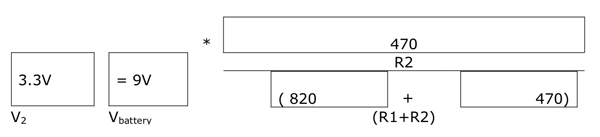
Using the diagram and the resistors in the lesson kit, build a voltage divider using the 9V battery, R1=820ohm, and R2=470ohm.
What voltage would you expect?
|
|
|
* |
|
||||
| R2 | |||||||
|
+ |
|
|||||
| V2 | Vbattery | (R1+R2) | |||||
What voltage did you measure?
|
|
Step 4: Building a Voltage Divider for a Desired Output
Using the voltage divider circuit, select R1 and R2 from the lesson kit to produce the following output voltages
| V2 | Vbattery | R1 | R2 | V2 calculated | V2 measured |
| 2.0V
|
|
||||
| 3.0V
|
|
||||
| 5.0V
|
|
||||
| 7.0V
|
|
Step 5: Building a Light Emitting Diode circuit
A circuit to illuminate a Light Emitting Diode (LED) is very similar to a Voltage Divider circuit. An LED circuit replaces R1 with the LED. For an LED in this configuration, V1 will be a constant voltage, regardless of the total current. Therefore, for these circuits, V2 is also known. LED’s require a certain amount of current for optimal operation. This is called the bias current. Therefore, if V2 and bias current are known, a value for R2 can be calculated.
As the name implies, LED’s are diodes and they will only illuminate when installed with the proper polarity. For this circuit, the flatted side should point towards R2
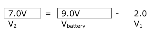
If R1 is replaced with an LED that has a voltage V1 of 2.0V and requiring a bias current of 20mA, (0.020A) determine the following
What is the value of V2?
|
|
= |
– |
2.0 |
|
| V2 | Vbattery | V1 |
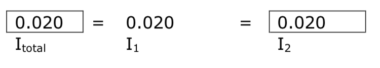
What is the value of Itotal
|
|
= |
0.020 |
= |
|
| Itotal | I1 | I2 |
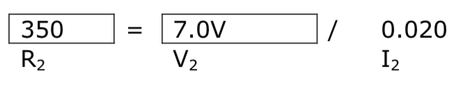
What is the resistor required for proper bias.
|
|
= |
|
/ |
0.020 |
| R2 | V2 | I2 |
Try a few resistors near the calculated value to find an optimal LED brightness. Measure V2 and compute the bias current.
| V2 measured | Vbattery | R2 | I2 calculated |
|
|
|||
|
|
|||
|
|
|||
|
|
Which resistor is the best choice? Why? What happens if the LED is installed backwards?
|
|
Lesson Goal
This lesson encourages students to use Ohm’s Law to design and build a voltage divider circuit. The voltage divider is one of the first circuits Electrical Engineering students learn and it is very useful for the study of Ohm’s law and associated concepts. During this lesson students derive and apply mathematical equations to build voltage divider circuits, including a circuit that will power a light emitting diode (LED).
Lesson Objectives
- Learn about Ohm’s Law.
- Use a digital multimeter to collect data.
- Explore the concepts of voltage and current.
- Analyze the electrical requirements of light emitting diodes (LED’s).
Materials
- Student handouts
- One set of materials for each group of students:
Note: The following materials list can be adapted for material on hand or for obtaining other voltage outputs. All materials can be reused.Multimeter Breadboard with Wire Set Calculator LED – Super Red, Clear Lens 9V Alkaline Battery 9V Battery Holder with Wire Leads Resistor: 100 ohm, Carbon Film, 1/2W, 5% Resistor: 150 ohm, Carbon Film, 1/2W, 5% Resistor: 220 ohm, Carbon Film, 1/2W, 5% Resistor: 330 ohm, Carbon Film, 1/2W, 5% Resistor: 470 ohm, Carbon Film, 1/2W, 5% Resistor: 560 ohm, Carbon Film, 1/2W, 5% Resistor: 680 ohm, Carbon Film, 1/2W, 5% Resistor: 820 ohm, Carbon Film, 1/2W, 5% Resistor: 910 ohm, Carbon Film, 1/2W, 5% Resistor: 1000 ohm, Carbon Film, 1/2W, 5%
Time Needed
Three to four 45 minute sessions
Procedure
Divide students into groups of two. Show students the various Student Resource Sheets. These may be read in class, or provided as reading material for the prior night’s homework.
Step 1: Reading Resistor Values
Students will find each of the following resistors in their lesson kit. They can review the handout on Resistor Color Codes and then determine the color codes for the following resistors. After finding each resistor in the lesson kit students can measure and record the resistance and determine whether the value is within the tolerance.
| Resistor | First
Band |
Second Band | Multiplier | Tolerance | Highest Resistance | Lowest Resistance | Measured | Within Tolerance? |
| 820 ohm | Gray | Red | Brown | 5% | 861 | 779 | ||
| 470 ohm | Yellow | Violet | Brown | 5% | 494 | 446 | ||
| 1K ohm
|
Brown | Black | Red | 5% | 1050 | 950 |
Step 2: Understanding Breadboards
Breadboards normally have rows of holes along each edge that are connected together. Then, running perpendicular to the edge holes, there are shorter rows with holes connected together. Oftentimes, the breadboards are split into two halves so that an integrated circuit can be placed in the middle of the board. For these boards, there will be a set of holes on each side of the split that are connected to each other, but are not connected across the split.
Invite students to explore the breadboards found in their kits. In the spaces provided on their worksheets, encourage students to draw diagrams of some of the connections on the breadboards and how the breadboards may be used to build a voltage divider circuit.
Step 3: Building a Voltage Divider
Using the diagram and the resistors in the lesson kit, invite students to build a voltage divider using the 9V battery, R1=820ohm, and R2=470ohm. Students can then predict and measure output voltages for their voltage dividers and record the information on their worksheets.
Assuming the 9V battery, R1=820ohm, and R2=470ohm.
What voltage would you expect?
What voltage did you measure?
Remember that the resistors have tolerances!!
Step 4: Building a Voltage Divider for a Desired Output
Using the voltage divider circuit, challenge students to select R1 and R2 from the lesson kit to produce the following output voltages:
| V2 | Vbattery | R1 | R2 | V2 calculated | V2 measured |
| 2.0V | 9V | 330
820 |
100
220 |
2.09 1.90 | |
| 3.0V | 9V | 680
910 |
330
470 |
2.94 3.07 | |
| 5.0V | 9V | 470 560 680 | 560 680 820 | 4.89
4.94 4.92 |
|
| 7.0V | 9V | 150 150
220 220 |
470 560
680 910 |
6.82
7.10 6.80 7.25 |
Step 5: Building a Light Emitting Diode circuit
A circuit to illuminate a Light Emitting Diode (LED) is very similar to a Voltage Divider circuit. An LED circuit replaces R1 with the LED. For an LED in this configuration, V1 will be a constant voltage, regardless of the total current. Therefore, for these circuits, V2 is also known. LED’s require a certain amount of current for optimal operation. This is called the bias current. Therefore, if V2 and bias current are known, students can calculate a value for R2.
As the name implies, LED’s are diodes. This means that they will only illuminate when installed with the proper polarity. In most cases, the flatted side of the LED needs to face towards the lower voltage. For this circuit, the flatted side should point towards R2
If R1 is replaced with an LED that has a voltage V1 of 2.0V and requiring a bias current of 20mA, (0.020A) determine the following:
What is the value of V2?
What is the value of Itotal
What is the resistor required for proper bias.
Try a few resistors near the required resistor value. Measure V2 and compute the bias current.
| V2 measured | Vbattery | R2 | I2 calculated |
| 7.0 | 9.0 | 220 | 32mA |
| 7.0 | 9.0 | 330 | 21mA |
| 7.0 | 9.0 | 470 | 15mA |
Which resistor is the best choice? Why?
Many correct answers are possible, depending on the actual resistor value and the parameters for the particular LED. Students should be encouraged to try different resistors to find a pleasing LED brightness, without being out of specified parameters.
Appendix 1: Equations for Series and Parallel Resistance
By applying basic concepts and Ohm’s Law, the equations for series and parallel resistance can be derived.
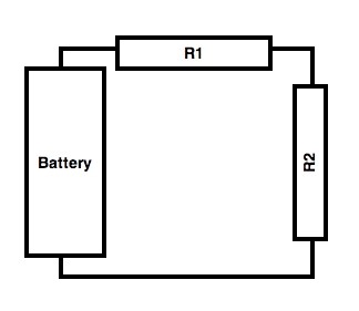 |
For a series circuit, R1 is said to be in series with R2. For these circuits, the currentflowing through each device in series is the same. Adding the voltages across each element in series is equal to the total (battery) voltage. |
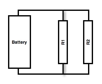 |
For a parallel circuit, R1 is said to be in parallel with R2. For these circuits, the voltage across each device in parallel is the same. Adding the current through each element in parallel is equal to the total (battery) current. |
These concepts can be used to derive the equations for series and parallel resistors.
Series Resistors
I1 = I2 = Itotal
Vbattery = V1 +V2 V1 = I1*R1
V2 = I2*R2
Vbattery = Itotal * Rtotal
Substituting, and dividing by Itotal
Itotal * Rtotal = I1*R1 + I2*R2
Rtotal = R1 + R2
Parallel Resistors
Vbattery = V1 = V2 Itotal = I1 + I2
Substituting, and dividing by Vbattery
Vbattery/Rtotal = V1/R1 + V2/R2
1/Rtotal = 1/R1 + 1/R2
Solving for Rtotal
Rtotal = (R1*R2)/(R1+R2)
Appendix 2: Matrix of Possible Voltage Outputs
For the specified list of resistors and a 9V battery, the following output voltages are possible:
| Output Voltage | 100 | 150 | 220 | 330 | 470 | 560 | 680 | 820 | 910 | 1000 |
| 100 | 4.50 | 3.60 | 2.81 | 2.09 | 1.58 | 1.36 | 1.15 | 0.98 | 0.89 | 0.82 |
| 150 | 5.40 | 4.50 | 3.65 | 2.81 | 2.18 | 1.90 | 1.63 | 1.39 | 1.27 | 1.17 |
| 220 | 6.19 | 5.35 | 4.50 | 3.60 | 2.87 | 2.54 | 2.20 | 1.90 | 1.75 | 1.62 |
| 330 | 6.91 | 6.19 | 5.40 | 4.50 | 3.71 | 3.34 | 2.94 | 2.58 | 2.40 | 2.23 |
| 470 | 7.42 | 6.82 | 6.13 | 5.29 | 4.50 | 4.11 | 3.68 | 3.28 | 3.07 | 2.88 |
| 560 | 7.64 | 7.10 | 6.46 | 5.66 | 4.89 | 4.50 | 4.06 | 3.65 | 3.43 | 3.23 |
| 680 | 7.85 | 7.37 | 6.80 | 6.06 | 5.32 | 4.94 | 4.50 | 4.08 | 3.85 | 3.64 |
| 820 | 8.02 | 7.61 | 7.10 | 6.42 | 5.72 | 5.35 | 4.92 | 4.50 | 4.27 | 4.05 |
| 910 | 8.11 | 7.73 | 7.25 | 6.60 | 5.93 | 5.57 | 5.15 | 4.73 | 4.50 | 4.29 |
| 1000 | 8.18 | 7.83 | 7.38 | 6.77 | 6.12 | 5.77 | 5.36 | 4.95 | 4.71 | 4.50 |
Appendix 3: Advanced Equations for Voltage Divider Ratios
The ratio of the battery voltage and the desired voltage can be used to determine the goal ratio of the two resistors. Knowing this ratio is very helpful when choosing from a limited selection of resistors.
Starting with the Voltage Divider Equation
V2 = Vbattery * (R2)/(R1 +R2)
The ratio of the voltage is represented by
V2/Vbattery = R2/(R1 + R2)
Invert the terms and solve for a simpler ratio of resistors
Vbattery/V2 = (R1 +R2)/R2
Vbattery/V2 = (R1/R2) + (R2/R2)
Vbattery/V2 = R1/R2 + 1
(Vbattery/V2) -1 = R1/R2 R1/R2 = (Vbattery/V2) -1
Consider the requirement for a 5V supply, using a 9V battery. Search for two resistors that obey the following proportion.
R1/R2 = (Vbattery/V2) -1
R1/R2 = (9/5) – 1
R1/R2 = 0.8
Using this ratio, it is immediately clear that R1=820 and R2=1000 will produce the desired voltage.
Voltage Divider Information Sheet
A Voltage Divider is used to produce a desired output voltage, using resistors in series.
The output voltage (voltage across R2) is proportional to the ratio of R1 and R2
Using Ohm’s Law, compute the Voltage across R1 and R2 and the total resistance
V1 = I1*R1 — where V1 is the voltage across R1, and I1 is the current through R1
V2 = I2*R2 — where V2 is the voltage across R2, and I2 is the current through R2
Vbattery = Itotal * Rtotal — where Vbattery is the battery voltage and Rtotal is the total resistance
Since R1 and R2 are in series, the total resistance is known.
Rtotal = R1 + R2
Since R1 and R2 are in series, the current through each resistor is the same as the total current
Itotal = I1 = I2
Solving for V2
I2 = V2/R2
Itotal = Vbattery/Rtotal = Vbattery/(R1+R2)
I2 = Itotal
V2/R2 = Vbattery/(R1 +R2)
V2 = Vbattery(R2/(R1+R2))
Therefore, the voltage across R2 can be determined by controlling the ratio of R2 to the total resistance, R1 + R2.
Downloadable Student Certificate of Completion