Sketching Circuits
This lesson explores conductivity and introduces students to the new technique of drawing electrical pathways for circuitry with pens. Students will design, and build a simple circuit using drawn connectors and construct a device for testing materials for conductivity.
- Learn about alternatives to wiring in electrical circuitry.
- Learn about the electrical properties of different materials.
- Learn how conductors and insulators react to electric current.
- Learn to predict outcomes and draw conclusions.
- Learn about teamwork and working in groups.
Age Levels: 8-12
Build Materials (For each team)
Required Materials
- Paper
- Pencil
- Ruler
- Circuit Scribe Kit (available on Amazon, from manufacturer, or other sites) (Note: we recommend purchasing additional Circuit Scribe Pens which are sold more cost effectively in sets.)
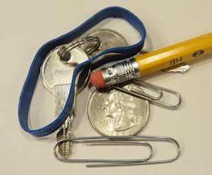
Testing Materials
- Conductivity testing:
- Metal paper clip
- Plastic caps
- Paper
- Rubber eraser
- Aluminum foil
- Metal pen
- Rubber band
- Pencil
- Cork
- Coin
- Key
Materials
- Conductivity testing:
- Metal paper clip
- Plastic caps
- Paper
- Rubber eraser
- Aluminum foil
- Metal pen
- Rubber band
- Pencil
- Cork
- Coin
- Key
Process
Each team should use their “test” circuit to evaluate a range of materials. They should document their findings.
Design Challenge
You are a team of engineers given the challenge of creating a simple circuit using a conductive pen instead of wiring. Because the paper can be folded, you have the opportunity to be very creative! Your design must incorporate two LEDs and allow for someone to interact with your circuit. You may be creative and draw a flower that lights up, set up an interactive quiz, or anything which lights up two LEDs.
Criteria
- Must include two LEDs.
- Must allow for someone to interact with it.
- Be creative.
Constraints
- Use only the materials provided.
- Only use special pen for lines that require current to flow.
- Break class into teams of 3-4.
- Hand out the Sketching Circuits worksheet, as well as some sheets of paper for sketching designs.
- Discuss the topics in the Background Concepts Section.
- Review the Engineering Design Process, Design Challenge, Criteria, Constraints and Materials.
- Provide each team with their materials.
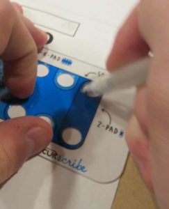
- Explain that students must develop a circuit using the Circuit Scribe kit that can light an LED. Students should be encouraged to be creative; suggest viewing online samples for inspiration that makes use of the flexibility of the conductive pen. The lesson includes a sample voting circuit, which could be used for younger students to replicate or as an example.
- Announce the amount of time they have to design and build (1 hour recommended).
- Use a timer or an on-line stopwatch (count down feature) to ensure you keep on time. (www.online-stopwatch.com/full-screen-stopwatch). Give students regular “time checks” so they stay on task. If they are struggling, ask questions that will lead them to a solution quicker.
- Students meet and develop a plan for their circuit. They should draw a schematic of their planned drawn circuit project with regular pencil or pen and review the idea and circuitry plan with the teacher.
- Once the plan is approved, teams build their circuit.
- Teams use the “tester” circuit to evaluate a range of materials.
- As a class, discuss the student reflection questions.
- For more content on the topic, see the “Digging Deeper” section.
Tips
- Teachers should consider distributing the student resource sheets as reading material/homework for the night before the activity will be conducted in class.
- Suggested solution examples for the simple circuit and the conductive test are available on the student worksheet.
- The Circuit Scribe kit is a safe, basically fail-proof way for younger students to experiment with circuits. The components are magnetized and attach to a metal plate (provided). Everything snaps in place and there are many options for experimentation. Contents include:
- Circuit Scribe pen, with silver and water-based non-toxic ink.
- Steel plate that is placed under any paper you use (paper not included with kit, but copy paper, construction paper, others will work)
- Components (LED, Battery connection, switches, etc.) are incorporated into magnetic modules that snap onto the paper (with steel sheet underneath). Each component has embedded circuitry so there is no need for student wiring or soldering.
- Circuit stencil to help students draw circles at the exact width of each component.
- There are several configurations of Circuit Scribe kits…ranging from the Mini Kit which has fewer components and a smaller pen, to a large maker kit with many components.
- The pens will run out eventually, so purchasing a couple of extra pens might be wise. You can order from the manufacturer, from school or electrical supply companies, or from online retailers such as Amazon.
- There are ways to attempt this lesson using graphite pencils, which does work, but has inconsistent results based on graphite quality, density, and paper, and requires manual connections between components. A graphite test could be an extension idea for some students.
Extension Idea
Challenge students to use other components in the kit, such as a switch or slide potentiometer (depending on which kit is used).
Student Reflection (engineering notebook)
- Were you able to create a circuit that could test for conductivity?
- Did you need to redesign your original pencil plan prior to building your final circuit? If so, what changed?
- Do you think that drawing a circuit is easier than working with wires? Are there any reasons why you think a wire circuit would be more appropriate?
- Describe a design that another student team developed that you thought was particularly creative!
- How do you think paper circuits might be used in everyday life? Would this be a new product, or adapting or improving an existing product?
- Were there any materials that you tested that surprised you?
- Why is it important to know whether a material is an insulator or a conductor?
Time Modification
The lesson can be done in as little as 1 class period for older students. However, to help students from feeling rushed and to ensure student success (especially for younger students), split the lesson into two periods giving students more time to brainstorm, test ideas and finalize their design. Conduct the testing and debrief in the next class period.
What is a Simple Circuit?
A simple circuit consists of three minimum elements that are required to complete a functioning electric circuit: a source of electricity (battery), a path or conductor on which electricity flows (wire) and an electrical resistor (lamp) which is any device that requires electricity to operate. The illustration below shows a simple circuit containing, one battery, two wires, a switch, and a bulb. The flow of electricity is from the high potential (+) terminal of the battery through the bulb (lighting it up), and back to the negative (-) terminal, in a continual flow when the switch is in the on position so current can flow
Schematic Diagram of a Simple Circuit
The following is a schematic diagram of the simple circuit showing the electronic symbols for the battery, switch, and bulb.

What Are Conductors and Insulators?
Conductors/Conductivity
Conductivity is the ability or power to conduct or transmit heat, electricity, or sound.
Conductors are materials that electricity easily passes through, that do not resist the flow of electricity. Examples are copper, aluminum, steel, silver, gold, electrolytes. Not all materials conduct electricity equally well.
Insulators
Insulators are materials that resist the flow of electricity, so electricity does not easily pass through. Examples are plastic, wood, rubber, cloth, air, glass. Some materials are better electricity insulators than others.
What are LEDs?

A Light-Emitting Diode – or LED — is a semiconductor device built to emit light when activated. Different chemicals give different LEDs their colors. When powered at the proper level, they can last much longer than incandescent light bulbs and do not break easily. They can display many different colors, can be very small, and are extremely efficient. Most of the energy they consume makes light, not heat. Most LEDs are very small, less than 1 mm, and so can be integrated into many products.
History

The first visible-spectrum (red) LED was developed in 1962 by Nick Holonyak, Jr. while working at General Electric. In 1972, M. George Craford, a former graduate student of Holonyak, invented the first yellow LED and improved the brightness of red and red-orange LEDs by a factor of ten. In 2014, the Nobel Prize in Physics was awarded to a team of scientists (Isamu Akasaki, Hiroshi Amano, and Shuji Nakamura) “for the invention of efficient blue light-emitting diodes which has enabled bright and energy-saving white light sources” While red and green LEDs had been available for many years at that time, the blue LEDs were a big challenge for scientists and engineers around the world. The blue version was needed to be able to mix with the red and green ones to produce white light…without white light we would not have had LED-based computer and TV screens.

Color and Shape Selection
LEDs are produced in many shapes and sizes, and while the color of the plastic lens is usually the same color as the light emitted, this is not always true. Many blue LEDs actually have clear or colorless plastic lenses, like the one to the right.
Applications

At first, LEDs were used as indicator lamps for simple electronic devices, where they replaced small incandescent bulbs and allowed products to be smaller. They were soon popularized and used in digital clocks and calculators. Quickly, manufacturers and consumers found that the small size and efficiency of these little lights made them the perfect choice for many applications. As an example, a white LED lightbulb converts over 50% of the electricity it uses into light…an incandescent bulb only converts about 4% into light. So now the applications are widespread…from car headlamps and taillights, camera flashes, and computer and television screens. If you look closely at your local traffic lights, you may find that what looks like a big bulb from a distance is actually a round pattern of red, green and yellow LEDs!
Internet Connections
Recommended Reading
- DK Eyewitness Books: Electricity (ISBN: 978-1465408990)
- Electronics for Kids: Play with Simple Circuits (ISBN: 978-1593277253)
- Teach Yourself Electricity and Electronics (ISBN: 978-1259585531)
Writing Activity
Write an essay (or paragraph depending on age) describing how the ability to draw circuitry could potentially impact or improve a product we use every day.
Alignment to Curriculum Frameworks
Note: Lesson plans in this series are aligned to one or more of the following sets of standards:
- U.S. Science Education Standards (http://www.nap.edu/catalog.php?record_id=4962)
- U.S. Next Generation Science Standards (http://www.nextgenscience.org/)
- International Technology Education Association’s Standards for Technological Literacy (http://www.iteea.org/TAA/PDFs/xstnd.pdf)
- U.S. National Council of Teachers of Mathematics’ Principles and Standards for School Mathematics (http://www.nctm.org/standards/content.aspx?id=16909)
- U.S. Common Core State Standards for Mathematics (http://www.corestandards.org/Math)
- Computer Science Teachers Association K-12 Computer Science Standards (http://csta.acm.org/Curriculum/sub/K12Standards.html)
Next Generation Science Standards (grades 3-5, middle school)
Students who demonstrate understanding can:
- 3-5-ETS1-1. Define a simple design problem reflecting a need or a want that includes specified criteria for success and constraints on materials, time, or cost.
- 3-5-ETS1-2. Generate and compare multiple possible solutions to a problem based on how well each is likely to meet the criteria and constraints of the problem.
- 3-5-ETS1-3. Plan and carry out fair tests in which variables are controlled and failure points are considered to identify aspects of a model or prototype that can be improved.
- 4-PS3-2. Make observations to provide evidence that energy can be transferred from place to place by sound, light, heat, and electric currents.
- 4-PS3-4. Apply scientific ideas to design, test, and refine a device that converts energy from one form to another.
- MS-ETS1-1. Define the criteria and constraints of a design problem with sufficient precision to ensure a successful solution, taking into account relevant scientific principles and potential impacts on people and the natural environment that may limit possible solutions.
- MS-ETS1-2. Evaluate competing design solutions using a systematic process to determine how well they meet the criteria and constraints of the problem.
- MS-ETS1-3. Analyze data from tests to determine similarities and differences among several design solutions to identify the best characteristics of each that can be combined into a new solution to better meet the criteria for success.
- MS-ETS1-4. Develop a model to generate data for iterative testing and modification of a proposed object, tool, or process such that an optimal design can be achieved.
U.S. Common Core State Standards for Mathematics (grades 3-5)
- Grade Three: Represent and Interpret Data (CCSS.MATH.CONTENT.3.MD.B.4)
- Grade Four: Represent and Interpret Data (CCSS.MATH.CONTENT.4.MD.B.4)
- Grade Five: Represent and Interpret Data (CCSS.MATH.CONTENT.5.MD.B.2)
International Technology Education Association’s Standards for Technological Literacy (grades 3-5)
- Chapter 8 – The Attributes of Design
- Definitions of Design
- Requirements of Design
- Chapter 9 – Engineering Design
- Engineering Design Process
- Creativity and Considering all ideas
- Models
- Chapter 10 – The Role of Troubleshooting, Research and Development, Invention, and Experimentation in Problem Solving
- Troubleshooting
- Invention and innovation
- Experimentation
- Chapter 11 – Apply the Design Process
- Collect information
- Visualize a solution
- Test and evaluate solutions
- Improve a design
- Chapter 16 – Energy and Power Technologies
- Energy comes in different forms
- Tools, machines, products and systems

 Industrial Engineering
 Computer Engineering
Planning
You and your team will be creating a simple circuit using a conductive pen instead of wiring. Because the paper can be folded, you have the opportunity to be very creative! You may use the separate worksheet to build your own voting station…or come up with your own idea that incorporates two LEDs and allows for someone to interact with your circuit. You may be creative and draw a flower that lights up, set up an interactive quiz, or anything which lights up two LEDs. You should conserve the special pen for lines that require current to flow and other drawing tools like colored pencils, crayons, or markers for other decorations.
In the box below, draw with a normal pencil your planned circuit — you will want to save the special pen for the final version. Be sure to mark where your battery and LED will be placed and consider any folding you might need to factor into the design. You can use the following electronic symbols in your sketch:
LED: 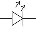 Battery:
You can use the template that comes with your kit to draw the circles to match the magnetic base of each component.
Once your teacher approves the planned design your team may move on to construction!
|
|
Drawing, Building, and Testing
Using your approved pencil sketch as a plan, create your paper circuit. Remember to use the circuit pen only for lines necessary to carry current and use other drawing tools for any instructions, decorations, or other writing needed.
Once complete, answer the following questions:
- Did you need to redesign your original pencil plan prior to building your final circuit? If so, what changed?
- Do you think that drawing a circuit is easier than working with wires? Are there any reasons why you think a wire circuit would be more appropriate?
- Describe a design that another student team developed that you thought was particularly creative!
- How do you think paper circuits might be used in everyday life? Would this be a new product, or adapting or improving an existing product?
Conductive Material Test
Now that you’ve built a simple circuit, try building a circuit that could be used to test a range of materials (provided to you) for conductivity. With an LED included in your testing circuit you will be able to see if a material is a conductor if it lights up!
As before, in the box below, draw with a normal pencil your planned conductive testing circuit. Once your teacher approves the planned design your team may build it.
Conductive Testing
In the box below, document the materials you examined in your conductive test circuit, and include your results.
| Material Tested | Insulator or Conductor | Observations |
Review and Reflections
- Were you able to create a circuit that could test for conductivity?
- Were there any materials that you tested that surprised you?
- Why is it important to know whether a material is an insulator or a conductor?
Student Voting Worksheet:
YES NO
Downloadable Student Certificate of Completion