Series and Parallel Circuits
Sponsored Lesson by KEYSIGHT Technologies

This lesson demonstrates simple circuits and the differences between parallel and serial circuit design and functions. Students work in teams to predict the difference between the two circuit designs and then build examples of the two different circuits using wires, bulbs, and batteries.
- Learn that different circuit designs result in different electrical behaviors.
- Learn about current flow and the operational differences between series and parallel circuits.
- Learn to predict outcomes and draw conclusions.
- Learn about teamwork and working in groups.
Age Levels: 8 – 14
Build and Testing Materials (For each team)
Required Materials (2 sets for each team)
- 6 pieces of bell wire (6″ each) with ends stripped
- Battery holder
- Socket
- Three or more 1.5 volt bulbs
- Size D batteries
Design Challenge
You are a team of engineers working together to design a system where one switch can turn on multiple lights. An example might be a string of lights.
Criteria
- Must diagram a parallel circuit
- Must build and test both a series and parallel circuit
Constraints
Use only the materials provided.
- Break class into teams of 2-4.
- Hand out the Series and Parallel Circuits worksheet, as well as some sheets of paper for sketching designs.
- Discuss the topics in the Background Concepts Section. Provide definitions of Series and Parallel circuits and discuss the differences.
- Review the Engineering Design Process, Design Challenge, Criteria, Constraints and Materials.
- Provide each team with their materials (2 sets for each team). Before students get started building, consider providing definitions of Series and Parallel circuits and discuss the differences.
- Series Circuits: Electricity has only one path on which to travel.
- Parallel Circuits: Electricity has more than one path on which to travel.
- Explain that each team must make a series and parallel circuit. Instruct them to examine the schematic of a series circuit on the Student Worksheet and draw their own plan for a parallel circuit.
- Announce the amount of time they have to make their circuits (1 hour recommended).
- Use a timer or an on-line stopwatch (count down feature) to ensure you keep on time. (www.online-stopwatch.com/full-screen-stopwatch). Give students regular “time checks” so they stay on task. If they are struggling, ask questions that will lead them to a solution quicker.
- Teams build their circuits.
- After the teams build both circuits, have them make the following predictions and record them on the Student worksheet:
● Do you think a string of lights are an example of parallel or series bulbs in a circuit? Explain why.
● Do you think the bulbs in the parallel circuit or the series circuit will burn brighter? Explain why.
● If you remove a bulb in your parallel circuit, will the other bulb(s) still light? Explain why.
● If you remove a bulb in your series circuit, will the other bulb(s) still light? Explain why. - Have each student group test their predictions using their circuits, and compare their results to their predictions.
- As a class, discuss the student reflection questions.
- For more content on the topic, see the “Digging Deeper” section.
Student Reflection (engineering notebook)
- Were your predictions about the brightness of the bulbs accurate?If not, what happened that was different from what your group expected?
- Were your predictions about what happened if a bulb was removed from the parallel and serial circuits accurate?If not, what happened that was different from what your group expected?
Tips
- Teachers may want to set up the series circuit before class and ask students to create the parallel circuit to save time.
- Teachers should consider distributing the student resource sheets as reading material/ homework for the night before the activity will be conducted in class.
- Encourage students to compare all the circuits built by different student groups.
Time Modification
The lesson can be done in as little as 1 class period for older students. However, to help students from feeling rushed and to ensure student success (especially for younger students), split the lesson into two periods giving students more time to brainstorm, test ideas and finalize their design. Conduct the testing and debrief in the next class period.
What is a Simple Circuit?
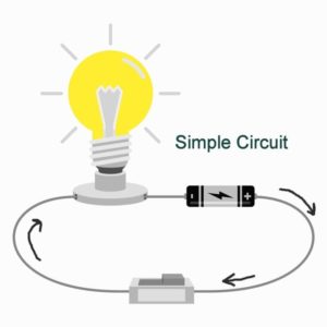
A simple circuit consists of three minimum elements that are required to complete a functioning electric circuit: a source of electricity (battery), a path or conductor on which electricity flows (wire) and an electrical resistor (lamp) which is any device that requires electricity to operate. The illustration below shows a simple circuit containing, one battery, two wires, a switch, and a bulb. The flow of electricity is from the high potential (+) terminal of the battery through the bulb (lighting it up), and back to the negative (-) terminal, in a continual flow when the switch is in the on position, so current can flow.
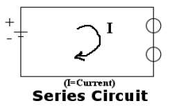
Schematic Diagram of a Simple Circuit
The following is a schematic diagram of the simple circuit showing the electronic symbols for the battery, switch, and bulb.

Series and parallel describes two different types of circuit arrangements. Each arrangement provides a different way for electricity to flow throughout a circuit.
Series Circuits
In a series circuit, electricity has only one path on which to travel. In the example to the right, two bulbs are powered by a battery in a series circuit design. Electricity flows from the battery to each bulb, one at a time, in the order they are wired to the circuit. In this case, because the electricity can only flow in one path, if one of the bulbs blew out, the other bulb would not be able to light up because the flow of electric current would have been interrupted. In the same way, if one bulb was unscrewed, the current flow to both bulbs would be interrupted.
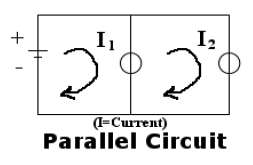
Parallel Circuits
In a parallel circuit, electricity has more than one path on which to travel. In the example to the right, two bulbs are powered by a battery in a parallel circuit design. In this case, because the electricity can flow in more than one path, if one of the bulbs blew out, the other bulb would still be able to light up because the flow of electricity to the broken bulb would not stop the flow of electricity to the good bulb. In the same way, if one bulb were unscrewed, it would not prevent the other bulb from lighting up.
What about Resistance?
The flow of electricity depends on how much resistance is in the circuit. In our examples, the bulbs provide resistance. In a series circuit, the resistance in the circuit equals the total resistance of all the bulbs. The more bulbs in the circuit, the dimmer they will light. In a parallel circuit, there are multiple paths through which current can flow, so the resistance of the overall circuit is lower than it would be if only one path was available. The lower resistance means that the current will be higher and the bulbs will burn brighter compared to the same number of bulbs arranged in a series circuit.
- Circuit: The loop that electricity flows through. A circuit begins at a power source, such as a battery, and flows through wires and electrical components (such as lights, motors, etc.).
- Conductor: Material that allows electricity to flow through it.
- Criteria: Conditions that the design must satisfy like its overall size, etc.
- Engineers: Inventors and problem-solvers of the world. Twenty-five major specialties are recognized in engineering (see infographic).
- Engineering Design Process: Process engineers use to solve problems.
- Engineering Habits of Mind (EHM): Six unique ways that engineers think.
- Insulator: Material that does not allow electricity to flow through it.
- Iteration: Test & redesign is one iteration. Repeat (multiple iterations).
- Parallel Circuit: Allows multiple paths for electricity to flow through.
- Prototype: A working model of the solution to be tested.
- Resistance: Insulation is measured in resistance. The more insulating a material, the more resistance it has.
- Series Circuit: Allows one path for electricity to flow through.
- Short Circuit: When wires that are not supposed to come in contact with each other touch.
Recommended Reading
- DK Eyewitness Series: Electricity (ISBN: 0751361321)
- Make Cool Gadgets for Your Room by Amy Pinchuk and Teco Rodriques (ISBN: 1894379128)
- My World of Science: Conductors and Insulators by Angela Royston (Heinemann Educational Books, ISBN: 0431137269)
Writing Activity
Write an essay (or paragraph depending on student age) describing how replacing one light on a string of bulbs with a “blinking” light would cause all the lights in the string to also blink. Is this an example of a parallel or series circuit? Why?
Alignment to Curriculum Frameworks
Note: Lesson plans in this series are aligned to one or more of the following sets of standards:
- U.S. Science Education Standards (http://www.nap.edu/catalog.php?record_id=4962)
- U.S. Next Generation Science Standards (http://www.nextgenscience.org/)
- International Technology Education Association’s Standards for Technological Literacy (http://www.iteea.org/TAA/PDFs/xstnd.pdf)
- U.S. National Council of Teachers of Mathematics’ Principles and Standards for School Mathematics (http://www.nctm.org/standards/content.aspx?id=16909)
- U.S. Common Core State Standards for Mathematics (http://www.corestandards.org/Math)
- Computer Science Teachers Association K-12 Computer Science Standards (http://csta.acm.org/Curriculum/sub/K12Standards.html)
National Science Education Standards Grades K-4 (ages 4 – 9)
CONTENT STANDARD A: Science as Inquiry
As a result of activities, all students should develop
- Abilities necessary to do scientific inquiry
- Understanding about scientific inquiry
CONTENT STANDARD B: Physical Science
As a result of the activities, all students should develop an understanding of
- Light, heat, electricity, and magnetism
CONTENT STANDARD E: Science and Technology
As a result of activities, all students should develop
- Understanding about science and technology
National Science Education Standards Grades 5-8 (ages 10 – 14)
CONTENT STANDARD A: Science as Inquiry
As a result of activities, all students should develop
- Abilities necessary to do scientific inquiry
- Understandings about scientific inquiry
CONTENT STANDARD B: Physical Science
As a result of their activities, all students should develop an understanding of
- Transfer of energy
CONTENT STANDARD E: Science and Technology
As a result of activities, all students should develop
- Understandings about science and technology
Next Generation Science Standards Grades 3-5 (Ages 8-11)
Students who demonstrate understanding can:
- 4-PS3-4. Apply scientific ideas to design, test, and refine a device that converts energy from one form to another.
Standards for Technological Literacy – All Ages
Design
- Standard 8: Students will develop an understanding of the attributes of design.
- Standard 9: Students will develop an understanding of engineering design.
- Standard 10: Students will develop an understanding of the role of troubleshooting, research and development, invention and innovation, and experimentation in problem solving.

 Computer Engineering
Instructions
You are the engineer! You need to design a system where one switch can turn on multiple lights! An example might be a string of holiday lights. Now, construct both a series circuit and a parallel circuit using the batteries, wires, and bulbs provided to you. Your series circuit will look something like the drawing below:

Draw your own diagram below that illustrates how your Parallel Circuit will look:
|
|
Group Predictions
After you have constructed both a series and parallel bulb circuit, make some predictions on the following as a group:
1. Do you think holiday lights are an example of parallel or series bulbs in a circuit? Explain why:
2. Do you think the bulbs in the parallel circuit or the series circuit will burn brighter? Explain why:
3. If you remove a bulb in your parallel circuit, will the other bulb(s) still light? Explain why:
4. If you remove a bulb in your series circuit, will the other bulb(s) still light? Explain why:
Test and Results
Now test your predictions for questions 2, 3 and 4 above. Then respond to the questions below:
1. Were your predictions about the brightness of the bulbs accurate? If not, what happened that was different from what your group expected?
2. Were your predications about what happened if a bulb was removed from the parallel and serial circuits accurate? If not, what happened that was different from what your group expected?
Downloadable Student Certificate of Completion