LEDs and Resistors
This lesson explores LEDs and resistors and reviews the differences between parallel and series circuit design and functions.
Students will:
- Learn about LEDs, their application and history.
- Learn about resistors and their function in electrical circuitry.
- Learn about current flow and the operational differences between series and parallel circuits.
- Learn to predict outcomes and draw conclusions.
- Learn about teamwork and working in groups.
Age Levels: 8 – 12
Build Materials (For each team)
Required Materials
- 9V Battery clip connector
- 9V Battery
- Assortment of LEDs (different colors)
- Assortment of resistors (330Ω, 1KΩ, 2KΩ, 5KΩ, 10KΩ, 100KΩ – NOT below 330Ω)
- Simple solderless breadboard
Testing Materials
- Use build materials
Materials
- Use build materials
Process
- Instruct teams to make predictions before testing their circuits. Now that their basic LED was powered, what do they think would happen if they used a different strength resistor? They should consider the LED brightness in the initial test as a “5.” Then, make predictions in the box on the student worksheet.
- Students test their circuit designs. Using their predictions, they should switch the resistors to see what happens to the LED. Instruct them to BE SURE TO WAIT FOR TWO MINUTES AFTER THE BATTERY IS DETACHED BEFORE TOUCHING THE RESISTOR, AS IT CAN BE WARM OR HOT. Students should document their test results in the box on the student worksheet.
Design Challenge
You are a team of engineers and need to design and build a simple breadboard circuit that will power an LED.
Criteria
- Use a resistor to protect the LED from receiving current directly from the battery.
Constraints
- Use only the materials provided.
- Break class into teams of 3-4.
- Hand out the LEDs and Resistors worksheet, as well as some sheets of paper for sketching designs.
- Using the Background Concepts Section, discuss the different types of circuits. Give an overview of LEDs, resistors and breadboards and have a classroom or team discussion to confirm their understanding.
- Review the Engineering Design Process, Design Challenge, Criteria, Constraints and Materials.
- Instruct students to start brainstorming and sketching their circuits.
- Provide each team with their materials.
- Explain that students must design and build a simple breadboard circuit that will power an LED.
- Announce the amount of time they have to sketch and build (1 hour recommended).
- Use a timer or an on-line stopwatch (count down feature) to ensure you keep on time. (www.online-stopwatch.com/full-screen-stopwatch). Give students regular “time checks” so they stay on task. If they are struggling, ask questions that will lead them to a solution quicker.
- Students meet and develop a plan for their breadboard circuit. Instruct them to construct their circuit using the following guidelines:
1. The longer wire (or lead) on any LED should be attached to the positive side of the battery or circuit.
2. Current can only flow through the LED in one direction in this lesson.
3. Choose a 10kΩ resistor for the initial breadboard.
3. Attach the battery after your teacher has approved your breadboard.
4. Once the battery is attached, don’t touch the resistor as it may be warm or hot. It will cool within a minute or two after detaching the battery.
5. If your LED lights up, you are ready to move on to the testing phase! - Teams build their circuits.
- Instruct teams to make predictions before testing their circuits. Now that their basic LED was powered, what do they think would happen if they used a different strength resistor? They should consider the LED brightness in the initial test as a “5.” Then, make predictions in the box on the student worksheet.
- Students test their circuit designs. Using their predictions, they should switch the resistors to see what happens to the LED. Instruct them to BE SURE TO WAIT FOR TWO MINUTES AFTER THE BATTERY IS DETACHED BEFORE TOUCHING THE RESISTOR, AS IT CAN BE WARM OR HOT. Students should document their test results in the box on the student worksheet.
- As a class, discuss the student reflection questions.
- For more content on the topic, see the “Digging Deeper” section.
Student Reflection (engineering notebook)
- How close was your hypothesis to the actual result of your resistor testing?
- What surprised you about the results?
- If this LED was designed into a doorbell, which level of resistor would you think the best choice?Why?
- Did you find that any of your component parts malfunctioned? What happened? Do you think you received a defective part?
Time Modification
The lesson can be done in as little as 1 class period for older students. However, to help students from feeling rushed and to ensure student success (especially for younger students), split the lesson into two periods giving students more time to brainstorm, test ideas and finalize their design. Conduct the testing and debrief in the next class period.
What is a Simple Circuit?
A simple circuit consists of three minimum elements that are required to complete a functioning electric circuit: a source of electricity (battery), a path or conductor on which electricity flows (wire) and an electrical resistor (lamp) which is any device that requires electricity to operate. The illustration below shows a simple circuit containing, one battery, two wires, a switch, and a bulb. The flow of electricity is from the high potential (+) terminal of the battery through the bulb (lighting it up), and back to the negative (-) terminal, in a continual flow when the switch is in the on position so current can flow
Schematic Diagram of a Simple Circuit
The following is a schematic diagram of the simple circuit showing the electronic symbols for the battery, switch, and bulb.
![]()
What are Series and Parallel Circuits?
Series and parallel describes two different types of circuit arrangements. Each arrangement provides a different way for electricity to flow throughout a circuit.
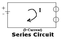
Series Circuits
In a series circuit, electricity has only one path on which to travel. In the example to the right, two bulbs are powered by a battery in a series circuit design. Electricity flows from the battery to each bulb, one at a time, in the order they are wired to the circuit. In this case, because the electricity can only flow in one path, if one of the bulbs blew out, the other bulb would not be able to light up because the flow of electric current would have been interrupted. In the same way, if one bulb was unscrewed, the current flow to both bulbs would be interrupted.
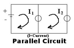
Parallel Circuits
In a parallel circuit, electricity has more than one path on which to travel. In the example to the right, two bulbs are powered by a battery in a parallel circuit design. In this case, because the electricity can flow in more than one path, if one of the bulbs blew out, the other bulb would still be able to light up because the flow of electricity to the broken bulb would not stop the flow of electricity to the good bulb. In the same way, if one bulb were unscrewed, it would not prevent the other bulb from lighting up.
What About Resistance?
The flow of electricity depends on how much resistance is in the circuit. In the example of lighting an LED, too low of a resistance could cause the LED to burn brightly and break….too high of a resistance would prevent the LED from lighting at all. Selecting the best, or optimal, resistor in a circuit for an application is part of the engineering design process.
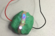
Resistance is measured in units called “Ohms” using the symbol Ω. The symbol Omega was selected as the symbol because it sounded like the name of the man who identified the measurement, Georg Ohm. In these pictures, the resistor on the left is stronger (a 10KΩ) than the resistor used on the right (a 330Ω). The left LED is dimmer because the resistor is stronger, holding back more current. The right LED is brighter because the resistor is weaker, allowing more current to power it.
What are LEDs?
A Light-Emitting Diode – or LED — is a semiconductor device built to emit light when activated. Different chemicals give different LEDs their colors. When powered at the proper level, they can last much longer than incandescent light bulbs and do not break easily. They can display many different colors, can be very small, and are extremely efficient. Most of the energy they consume makes light, not heat. Most LEDs are very small, less than 1 mm, and so can be integrated into many products.
History
The first visible-spectrum (red) LED was developed in 1962 by Nick Holonyak, Jr. while working at General Electric. In 1972, M. George Craford, a former graduate student of Holonyak, invented the first yellow LED and improved the brightness of red and red-orange LEDs by a factor of ten. In 2014, the Nobel Prize in Physics was awarded to a team of scientists (Isamu Akasaki, Hiroshi Amano, and Shuji Nakamura) “for the invention of efficient blue light-emitting diodes which has enabled bright and energy-saving white light sources” While red and green LEDs had been available for many years at that time, the blue LEDs were a big challenge for scientists and engineers around the world. The blue version was needed to be able to mix with the red and green ones to produce white light…without white light we would not have had LED-based computer and TV screens.
Color and Shape Selection
LEDs are produced in many shapes and sizes, and while the color of the plastic lens is usually the same color as the light emitted, this is not always true. Many blue LEDs actually have clear or colorless plastic lenses, like the one to the right.
Applications
At first, LEDs were used as indicator lamps for simple electronic devices, where they replaced small incandescent bulbs and allowed products to be smaller. They were soon popularized and used in digital clocks and calculators. Quickly, manufacturers and consumers found that the small size and efficiency of these little lights made them the perfect choice for many applications. As an example, a white LED lightbulb converts over 50% of the electricity it uses into light…an incandescent bulb only converts about 4% into light. So now the applications are widespread…from car headlamps and taillights, camera flashes, and computer and television screens. If you look closely at your local traffic lights, you may find that what looks like a big bulb from a distance is actually a round pattern of red, green and yellow LEDs!
What are Resistors?
A resistor limits or resists the electrical current that flows through a circuit. The energy of the electrons that pass through a resistor are changed to heat and/or light…so less current is available to whatever device (an LED for example) is next on the circuit. In working with this lesson, the resistors will become warm because they are converting electrical energy to heat. We have selected resistors that will be very safe to use but it is wise to not touch the resistor for a couple of minutes after disconnecting the circuit so they have a chance to cool.
Resistors are used in many different ways, frequently to protect components in a circuit from damage. In this lesson, the LEDs would likely burn out or break if put in a circuit without a resistor to protect them.
Standards in Color Coding Resistors
Identifying a resistor is an important skill when building a circuit. You have to know how a resistor will behave in a circuit. There are international standards so that engineers can assume consistency between parts.
A resistor’s value is determined by the colors that are printed on it in bands of some combination of black, brown, red, orange, yellow, green, blue, purple, gray, or white. Each color represents a different number as shown below:
0 – black
1 – brown
2 – red
3 – orange
4 – yellow
5 – green
6 – blue
7 – purple
8 – gray
9 – white
The last band on a resistor indicates tolerance, which is how accurate the resistor is. For example, a gold band represents a positive or negative 5% tolerance, while the silver band represents a positive or negative 10% tolerance.
- silver ±10%
- gold ±5%
- red ±2%
- brown ±1%
- If no fourth band is shown the tolerance is ±20%
Reading from left to right, the resistor shown has orange, orange, brown, then gold. The first two bands represent the numbers in the box above, so for the resistor in the photo we read 3 (for orange) and 3 (for orange). The last band gives the number of zeros to add at the end. For this resister because it is brown (1), we add just one zero to indicate a 330Ω (ohm) resistor, with a 5% tolerance.
Simple Breadboard Circuits
A breadboard is a board with internal wiring that allows circuits to be designed and tested without soldering. Individual components all have wires which are placed into the holes. They simply insert in the hole, and do not push all the way through to the other side. If the holes are in the same row on the same side they are connected internally, so it is easy to test different components and circuits and then make revisions! In the example to the right, the columns of two holes between the red and blue line are connected internally, as are all the rows. You can see the rows are numbered and the columns in the middle have letters at the top and bottom. Some plans for a circuit might indicate that part begin on E6 and end on D4, for example. Safety: a breadboard is safe to use as the wiring is internal, but avoid touching the connected ends of the battery to your skin. If you do, you may feel minor electricity. Also don’t touch the resistor when in use as it can get very hot.
Building a Simple Circuit
Step One: Insert the battery holder. In the image above you can see the leads from the battery holder in place in the breadboard. Note that the battery is not connected until the circuit is ready to test. The red wire is positive and the black wire is negative. Current will flow from the red through the circuit and back to the battery to the black connector. Note that the breadboard has a + above the row where the red wire is inserted and a – above the column where the black wire is inserted.
Step Two: Add a resistor. One end will need to be in a hole in the same column that the red battery wire is inserted…in this case it is in row 7 under the red + and the other end is in D6. It could have been any row or column instead of D6, but it must be in the same row as the longer lead to the LED.
Step Three: Add an LED. The longer lead on an LED must be the first in sequence in the path of current. So, note that this has been placed in the same row (6) as the resistor. The shorter end of the LED has been placed in the same column as the black battery connector, in row 5. It could have been placed in any hole in the black column.
Step Four: Connect a Battery. Snap the 9 volt battery into the connector to power the circuit.
This is a simple circuit on a breadboard, so we have been able to be flexible in selecting which holes to place the wires. Sometimes, if there are many components, the actual board might need to be organized more carefully.
Recommended Reading
- DK Eyewitness Books: Electricity (ISBN: 978-1465408990)
- Electronics for Kids: Play with Simple Circuits (ISBN: 978-1593277253)
- Teach Yourself Electricity and Electronics (ISBN: 978-1259585531)
Writing Activity
Write an essay (or paragraph depending on age) describing how the invention of LEDs have impacted the design of everyday products. Consider the energy efficiency of LEDs in your discussion.
Alignment to Curriculum Frameworks
U.S. Common Core State Standards for Mathematics (grades 3-5)
- Grade Three: Represent and Interpret Data (CCSS.MATH.CONTENT.3.MD.B.4)
- Grade Four: Represent and Interpret Data (CCSS.MATH.CONTENT.4.MD.B.4)
- Grade Five: Represent and Interpret Data (CCSS.MATH.CONTENT.5.MD.B.2)
International Technology Education Association’s Standards for Technological Literacy (grades 3-5)
- Chapter 8 – The Attributes of Design
- Definitions of Design
- Requirements of Design
- Chapter 9 – Engineering Design
- Engineering Design Process
- Creativity and Considering all ideas
- Models
- Chapter 10 – The Role of Troubleshooting, Research and Development, Invention, and Experimentation in Problem Solving
- Troubleshooting
- Invention and innovation
- Experimentation
- Chapter 11 – Apply the Design Process
- Collect information
- Visualize a solution
- Test and evaluate solutions
- Improve a design
- Chapter 16 – Energy and Power Technologies
- Energy comes in different forms
- Tools, machines, products and systems

Simple Circuit
A simple circuit consists of three elements: a source of electricity (battery), a path or conductor on which electricity flows (wire) and an electrical load (lamp) which is any device that requires electricity to operate. The illustration below shows a simple circuit containing a battery, two wires, and a low voltage light bulb. The flow of electricity is caused by excess electrons on the negative end of the battery flowing toward the positive end, or terminal, of the battery. When the circuit is complete, electrons flow from the negative terminal through the wire conductor, then through the bulb (lighting it up), and finally back to the positive terminal – in a continual flow.
Schematic Diagram of a Simple Circuit
The following is a schematic diagram of the simple circuit showing the electronic symbols for the battery, switch, and bulb.
What are Series and Parallel Circuits?
Series and parallel describes two different types of circuit arrangements. Each arrangement provides a different way for electricity to flow throughout a circuit.
Series Circuits
In a series circuit, electricity has only one path on which to travel. In the example to the right, two bulbs are powered by a battery in a series circuit design. Electricity flows from the battery to each bulb, one at a time, in the order they are wired to the circuit. In this case, because the electricity can only flow in one path, if one of the bulbs blew out, the other bulb would not be able to light up because the flow of electric current would have been interrupted. In the same way, if one bulb was unscrewed, the current flow to both bulbs would be interrupted.
Parallel Circuits
In a parallel circuit, electricity has more than one path on which to travel. In the example to the right, two bulbs are powered by a battery in a parallel circuit design. In this case, because the electricity can flow in more than one path, if one of the bulbs blew out, the other bulb would still be able to light up because the flow of electricity to the broken bulb would not stop the flow of electricity to the good bulb. In the same way, if one bulb were unscrewed, it would not prevent the other bulb from lighting up.
What About Resistance?
The flow of electricity depends on how much resistance is in the circuit. In the example of lighting an LED, too low of a resistance could cause the LED to burn brightly and break….too high of a resistance would prevent the LED from lighting at all. Selecting the best, or optimal, resistor in a circuit for an application is part of the engineering design process.
Resistance is measured in units called “Ohms” using the symbol Ω. The symbol Omega was selected as the symbol because it sounded like the name of the man who identified the measurement, Georg Ohm. In these pictures, the resistor on the left is stronger (a 10KΩ) than the resistor used on the right (a 330Ω). The left LED is dimmer because the resistor is stronger, holding back more current. The right LED is brighter because the resistor is weaker, allowing more current to power it.
What are LEDs?
A Light-Emitting Diode – or LED — is a semiconductor device built to emit light when activated. Different chemicals give different LEDs their colors. When powered at the proper level, they can last much longer than incandescent lightbulbs and do not break easily. They can display many different colors, can be very small, and are extremely efficient. Most of the energy they consume makes light, not heat. Most LEDs are very small, less than 1 mm, and so can be integrated in to many products.
History
The first visible-spectrum (red) LED was developed in 1962 by Nick Holonyak, Jr. while working at General Electric. In 1972, M. George Craford, a former graduate student of Holonyak, invented the first yellow LED and improved the brightness of red and red-orange LEDs by a factor of ten. In 2014, the Nobel Prize in Physics was awarded to a team of scientists (Isamu Akasaki, Hiroshi Amano, and Shuji Nakamura) “for the invention of efficient blue light-emitting diodes which has enabled bright and energy-saving white light sources” While red and green LEDs had been available for many years at that time, the blue LEDs were a big challenge for scientists and engineers around the world. The blue version was needed to be able to mix with the red and green ones to produce white light…without white light we would not have had LED-based computer and TV screens.
Color and Shape Selection
LEDs are produced many shapes and sizes, and while the color of the plastic lens is usually the same color as the light emitted, this is not always true. Many blue LEDs actually have clear or colorless plastic lenses, like the one to the right.
Applications
A resistor limits or resists the electrical current that flows through a circuit. The energy of the electrons that pass through a resistor are changed to heat and/or light…so less current is available to whatever device (an LED for example) is next on the circuit. In working with this lesson, the resistors will become warm because they are converting electrical energy to heat. We have selected resistors that will be very safe to use but it is wise to not touch the resistor for a couple of minutes after disconnecting the circuit so they have a chance to cool.
Standards in Color Coding Resistors
Identifying a resistor is an important skill when building a circuit. You have to know how a resistor will behave in a circuit. There are international standards so that engineers can assume consistency between parts.
A resistor’s value is determined by the colors that are printed on it in bands of some combination of black, brown, red, orange, yellow, green, blue, purple, gray, or white. Each color represents a different number as shown below:
| 0 – black
1 – brown 2 – red 3 – orange 4 – yellow |
5 – green
6 – blue 7 – purple 8 – gray 9 – white |
The last band on a resistor indicates tolerance, which is how accurate the resistor is. For example, a gold band represents a positive or negative 5% tolerance, while the silver band represents a positive or negative 10% tolerance.
- silver±10%
- gold±5%
- red±2%
- brown±1%
- If no fourth band is shown the tolerance is ±20%
Reading from left to right, the resistor shown has orange, orange, brown, then gold. The first two bands represent the numbers in the box above, so for the resistor in the photo we read 3 (for orange) and 3 (for orange). The last band gives the number of zeros to add at the end. For this resister because it is brown (1), we add just one zero to indicate a 330Ω (ohm) resistor, with a 5% tolerance.
Simple Breadboard Circuits
A breadboard is a board with internal wiring that allows circuits to be designed and tested without soldering. Individual components all have wires which are placed into the holes. They simply insert in the hole, and do not push all the way through to the other side. If the holes are in the same row on the same side they are connected internally, so it is easy to test different components and circuits and then make revisions! In the example to the right, the columns of two holes between the red and blue line are connected internally, as are all the rows. You can see the rows are numbered and the columns in the middle have letters at the top and bottom. Some plans for a circuit might indicate that part begin on E6 and end in D4, for example. Safety: a breadboard is safe to use as the wiring is internal, but avoid touching the connected ends of the battery to your skin. If you do, you may feel minor electricity. Also don’t touch the resistor when in use as it can get very hot.
Building a Simple Circuit
Step One: Insert the battery holder. In the image above you can see the leads from the battery holder in place in the breadboard. Note that the battery is not connected until the circuit is ready to test. The red wire is positive and the black wire is negative. Current will flow from the red through the circuit and back to the battery to the black connector. Note that the breadboard has a + above the row where the red wire is inserted and a – above the column where the black wire is inserted.
Step Two: Add a resistor. One end will need to be in a hole in the same column that the red battery wire is inserted…in this case it is in row 7 under the red + and the other end is in D6. It could have been any row or column instead of D6, but it must be in the same row as the longer lead to the LED.
Step Three: Add an LED. The longer lead on an LED must be the first in sequence in the path of current. So, note that this has been placed in the same row (6) as the resistor. The shorter end of the LED has been placed in the same column as the black battery connector, in row 5. It could have been placed in any hole in the black column.
Step Four: Connect a Battery. Snap the 9 volt battery into the connector to power the circuit.
This is a simple circuit on a breadboard, so we have been able to be flexible in selecting which holes to place the wires. Sometimes, if there are many components, the actual board might need to be organized more carefully.
Student Worksheet
Planning
You are a team of engineers and need to design and build a simple breadboard circuit that will power an LED. Then you’ll perform some experiments to help you learn about LEDs and resistors. You have been provided with several parts…including a breadboard, a battery and battery holder, some LEDs and some resistors. You’ll need a resistor to protect the LED from receiving current directly from the battery which would burn it out.
In the box below using appropriate electronic symbols, draw your planned circuit. Be sure to draw arrows showing the direction of current flow.\
ELECTRONIC SYMBOLS:
LED: Resistor: Battery:
Construction
Once your teacher has reviewed your plan, you can begin to construct your breadboard circuit. A few tips:
- The longer wire (or lead) on any LED should be attached to the positive side of the battery or circuit.
- Current can only flow through the LED in one direction in this lesson.
- Choose a 10kΩ resistor for the initial breadboard.
- Attach the battery after your teacher has approved your breadboard.
- Once the battery is attached, don’t touch the resistor as it may be warm or hot. It will cool within a minute or two after detaching battery.
If your LED was powered and lights up, you are ready to move on to the testing phase!
Hypothesis
Now that your basic LED was powered, what do you think would happen if you used a different strength resistor? Consider your LED brightness in the initial test as a “5.” Make predictions in the box below:
| Strength of Resistor
(Ω = OHMs) |
Observed LED brightness (scale 0-10, 10 brightest) | Anticipated LED brightness (scale 0-10, 10 brightest) |
| 330Ω | ? | |
| 2kΩ | ? | |
| 5kΩ | ? | |
| 10kΩ | 5 | |
| 100kΩ | ? |
Testing
With your predictions in the box above, switch the resistors to see what happens to the LED. BE SURE TO WAIT FOR TWO MINUTES AFTER THE BATTERY IS DETACHED BEFORE TOUCHING THE RESISTOR AS IT CAN BE WARM OR HOT.
| Strength of Resistor (Ω = OHMs) |
Observed LED brightness (scale 0-10, 10 brightest) |
| 330Ω | |
| 2kΩ | |
| 5kΩ | |
| 10kΩ | 5 |
| 100kΩ |
Reflection
Answer the questions below:
- How close was your hypothesis to the actual result of your resistor testing?
- What surprised you about the results?
- If this LED was designed into a doorbell, which level of resistor would you think the best choice?Why?
- Did you find that any of your component parts malfunctioned? What happened? Do you think you received a defective part?
Downloadable Student Certificate of Completion